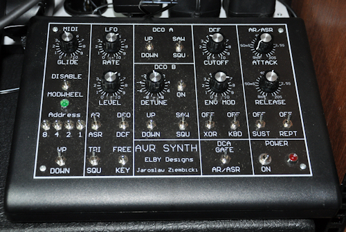
 The construction of this synthesizer was a project I did with my oldest daughter. She was always very interested in my electronics hobby so we decided to do a project together. I looked on the Internet for a project that wasn't too hard and found this AVRSynth32 at Elby Designs from Australia. I ordered it as a complete kit from Elby so it came with the case and the front panel, switches, leds, knobs etc. It is quite a nice synthesizers. It looks analog, but it actually is digital. More like an Virtual Analog it has a CPU that generates the analog waveforms and calculates the filters etc. But still it sounds quite analog actually. Not bad at all.
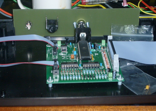
 In the picture on the right you can see the PCB when I just installed it in the case. It is not a very complicated PCB. There are also just three connectors on the back panel. A power socket, a big stereo jack for the audio output and a midi connector. It only has midi in to play on it. On the PCB is a little circuit for the midi input and there is an DA converter with very precise resistors. This circuit transforms the Digital signal from the CPU into the analog output signal. The rest is inputs to the CPU to read out the position of the switches and to measure the voltage from the potmeters. It is actually quite a simple but very efficient design.
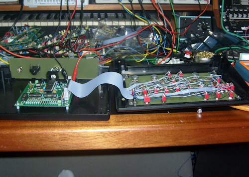
 And here you see the back of the front panel. What you see is NOT a PCB, it is the actually front panel. It is also printed on an epoxy layer. As you can see the switches and potmeters are all connected to a flat cable on the main PCB. They are all connected in a matrix that is scanned from the CPU. The documentation is not very extensive about everything but you can all find it in there. Again I would say this is not really a beginner project, but it was fun for sure. Also my daughter liked it a lot and when it was done we played a bit of music on it.
You can read more about the whole construction on my blog: http://synthnl.blogspot.com/search/label/AVRSynth